


1000 BASE-T铜质单模SFP模块GPSFP-GE-T
Product Details
Product Advantage
Product Parameter :
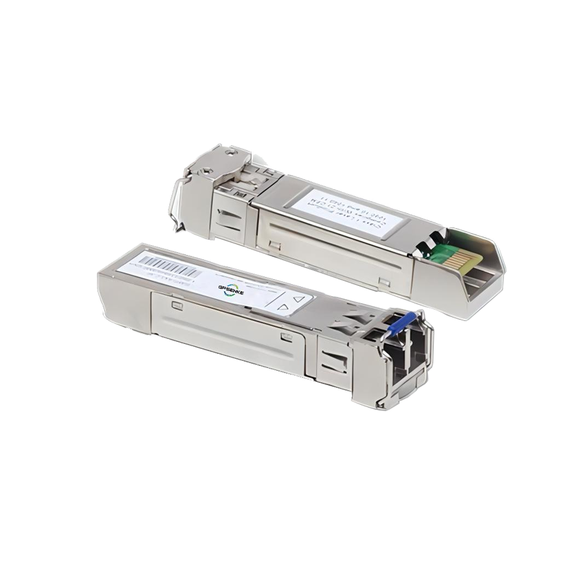
GPSFP-GE-T Copper Small Form Pluggable (SFP) transceivers are based on the SFP Multi Source Agreement (MSA). They are compatible with the Gigabit Ethernet standards as specified in IEEE STD 802.3. The 1000 BASE-T physical layer IC (PHY) can be accessed via I2C, allowing access to all PHY settings and features.
The GPSFP-GE-T uses the RX_LOS pin for link indication, and 1000BASE-X auto-negotiation should be disabled on the host system.
Part Number Ordering Information
Part Number | Data Rate (Gb/s) | Transmission Distance(m) | Link Indicator on RX_ LOS pin | TX_ disable with PHY | Temperature (oC) (Operating Case) |
GPSFP-GE-T | 1.25 | 100 | Yes | No | 0~70 commercial |
GPSFP-GE-T | 1.25 | 100 | Yes | No | - 10~80 Extended |
GPSFP-GE-T | 1.25 | 100 | Yes | No | -40~85 Industrial |
I. Absolute Maximum Ratings
It has to be noted that the operation in excess of any individual absolute maximum ratings might cause permanent damage to this module.
| Parameter | Symbol | Min | Max | Unit | Notes |
Storage Temperature | TS | -40 | 85 | oC | |
Power Supply Voltage | VCC | -0.5 | 3.6 | V | |
Relative Humidity (non-condensation) | RH | 5 | 95 | % |
II. Recommended Operating Conditions and Power Supply Requirements
Parameter | Symbol | Min | Typical | Max | Unit | Notes |
Operating Case Temperature |
TOP | 0 | 70 |
oC | commercial | |
- 10 | 80 | extended | ||||
-40 | 85 | industrial | ||||
Power Supply Voltage | VCC | 3.135 | 3.3 | 3.465 | V | |
Data Rate | 1.25 | Gb/s | ||||
Link Distance (SMF) | D | 100 | m |
III. General Description
IV. Pin Assignment and Pin Description
Figure1. Diagram of host board connector block pin numbers and names.
| PIN | Name | Name/Description | Notes |
| 1 | VEET | Transmitter Ground (Common with Receiver Ground) | 1 |
| 2 | TXFAULT | Transmitter Fault. | |
| 3 | TXDIS | Transmitter Disable. Laser output disabled on high or open. | |
| 4 | MOD_DEF(2) | Module Definition 2. Data line for Serial ID. | 2 |
| 5 | MOD_DEF(1) | Module Definition 1. Clock line for Serial ID | 2 |
| 6 | MOD_DEF(0) | Module Definition 0. Grounded within the module. | 2 |
| 7 | Rate Select | No connection required | |
| 8 | LOS | Loss of Signal indication. Logic 0 indicates normal operation. | |
| 9 | VEER | Receiver Ground (Common with Transmitter Ground) | 1 |
| 10 | VEER | Receiver Ground (Common with Transmitter Ground) | 1 |
| 11 | VEER | Receiver Ground (Common with Transmitter Ground) | 1 |
| 12 | RD- | Receiver Inverted DATA out. AC Coupled | |
| 13 | RD+ | Receiver Non-inverted DATA out. AC Coupled | 1 |
| 14 | VEER | Receiver Ground (Common with Transmitter Ground) | |
| 15 | VCCR | Receiver Power Supply | |
| 16 | VCCT | Transmitter Power Supply | |
| 17 | VEET | Transmitter Ground (Common with Receiver Ground) | 1 |
| 18 | TD+ | Transmitter Non-Inverted DATA in. AC Coupled. | |
| 19 | TD- | Transmitter Inverted DATA in. AC Coupled. | |
| 20 | VEET | Transmitter Ground (Common with Receiver Ground) | 1 |
Notes:
1. Circuit ground is connected to chassis ground.
2. Should be pulled up with 4.7k - 10k Ohms on host board to a voltage between 2.0 V and 3.6 V. MOD_DEF (0) pulls line low to indicate module is plugged in.
3. LVTTL compatible with a maximum voltage of 2.5V.
V. Power Supply Interface Electronic Characteristics
The GPSFP-GE-T has an input voltage range of 3.3 V ± 5%. The 4 V maximum voltage is not allowed for continuous operation.
Parameter | Symbol | Min | Typical | Max | Unit | Notes |
| Power Consumption | 1.2 | W | ||||
| Supply Current | Icc | 375 | mA | |||
| Input Voltage Tolerance | -0.3 | 4.0 | V | |||
| Surge | Surge | 30 | mV | |||
| Current | Current See Caution Note | |||||
Notes: Power consumption and surge current are higher than the specified values in the SFP MSA
VI. Low-Speed Signals Electronic Characteristics
MOD_DEF (1) (SCL) and MOD_DEF (2) (SDA) are open drain CMOS signals. Both MOD_ DEF (1) and MOD_DEF (2) must be pulled up to host_ VCC
| Parameter | Symbol | Min | Typical | Max | Unit | Notes |
| SFP Output LOW | VOL | 0 | 0.5 | V | 4.7k to 10k pull-up to host_ Vcc. | |
| SFP Output HIGH | VOH | host_ Vcc -0.5 | host_ Vcc +0.3 | V | 4.7k to 10k pull-up to host_ Vcc. | |
| SFP Input LOW | VIL | 0 | 0.8 | V | 4.7k to 10k pull-up to Vcc. | |
| SFP Input HIGH | VIH | 2 | Vcc + 0.3 | V | 4.7k to 10k pull-up to Vcc. |
VII. High-Speed Electrical Interface
All high-speed signals are AC-coupled internally.
| High-Speed Electrical Interface, Transmission Line-SFP | ||||||
| Parameter | Symbol | Min | Typical | Max | Unit | Notes |
| Line Frequency | fL | 125 | MHz | 5-level encoding, per IEEE 802.3 | ||
| Tx Output Impedance | Rx Input Impedance | 100 | Ohm | Differential | ||
| Rx Input Impedance | Zin,RX | 100 | Ohm | Differential | ||
| High-Speed Electrical Interface, Host-SFP | ||||||
| Single Ended Data Input Swing | Vinsing | 250 | 1200 | mV | Single ended | |
Single Ended | Voutsing | 350 | 800 | mV | Single ended | |
Data Output Swing | ||||||
| Rise/Fall Time | Tr,Tf | 175 | ps | 20%-80% | ||
Tx Input Impedance | Zin | 50 | Ohm | Single ended | ||
Rx Output Impedance | Zout | 50 | Ohm | Single ended | ||
VIII. General Specifications
| Parameter | Symbol | Min | Typical | Max | Unit | Notes |
| Data Rate | BR | 10 | 1000 | Mb/s | IEEE 802.3 compatible | |
Cable Length | L | 100 | m | Category 5 UTP. BER<10- 12 |